Auto-constrained Surface
![]()
The Auto-constrained surface command allows you to easily create a surface starting from wireframe elements and along one or two directions. This command allows you to select the elements by window, applies an internal sorting and proposes an automatic result. It is possible to select only a set of wireframe elements and/or two or four chains of edges.
Depending on your selection, this command may create a ruled surface, a lofted surface, a patch surface, a surface tangent to two surfaces/faces, etc.
Access
- Click the Auto-constrained
 icon in the Surfaces tab.
 - Type Auto in the Quick Search field and select Auto-constrained from the result list.
The Auto-constrained surface dialog box is displayed. ![]() (See dialog box.)
(See dialog box.)
Procedure
In the following steps, confirmation by Right Mouse click may be required if Multi-select ![]() is active in the Selection options.
is active in the Selection options.
- Click on the
 icon in the required Curves or Edges section of the dialog box to activate the selection mode of the corresponding entities.
 - Select the curves to be used for surface creation. You may use window selection.
and/or - Select reference edges to define tangency conditions.
- After entity selection, the dialog box displays different options allowing you to create different surface types.
Set the required parameters according to the result that you want to achieve. - Validate, either by a Right Mouse click or by clicking the
 icon in the dialog box.
![]() Notes:
Notes:
- The ribbon displays the suitable filter options for the entities that you are selecting.
- Pressing the [W] key of your keyboard allows you to toggle between wireframe and shaded preview display of the entity being created.
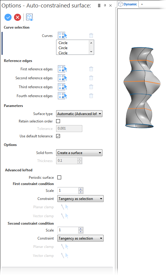
Auto-constrained Surfaces - Dialog Box Options
According to the selected elements, the following options are available:
Top Toolbar
![]()
![]()
![]()
These two icons at the top of the dialog box allow you to Apply the current values or to Cancel the current function.
Preview generation is Automatic if this option is active in the dialog box menu accessed by clicking on the  icon. If this option is not active, click on the
 ![]() icon. If preview generation is not possible, the icon is greyed out.
icon. If preview generation is not possible, the icon is greyed out.
Curve selection
|
Curves |
The curves defining the shape of the surface to be created may be selected individually or you may use window selection. Clicking on the |
Reference edges
|
First to Fourth reference edges |
Clicking on the |
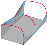
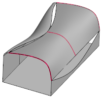
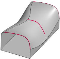
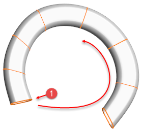
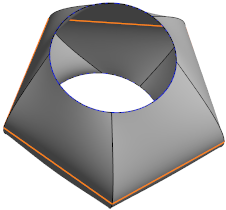
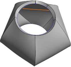
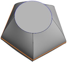
In the following example, the red curves were selected for shape definition. In the second image, without edge selection, a non-tangent new surface was created. In the third image, the blue edges were selected as the first and second reference edges creating a tangent surface:
Parameters
|
Surface type |
The contents of this drop-down list change according to the selected elements. It proposes the most convenient automatic solution and a list of alternatives. |
|
Retain selection order |
In some cases, it may be important to select the curves in a certain order to obtain the desired result. Activating this option creates the surface respecting the selection order. |
|
Tolerance |
This field is available when the Use default tolerance option is not active. It allows you to enter another tolerance in this input field. |
|
Use default tolerance |
Activate this option to apply the default tolerance. |
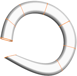
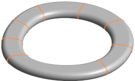
In the following example, the profiles were selected individually, starting from (1) in an anti-clockwise direction as shown in the first image. In the second image, the Retain selection order option is active:
Options
| Solid form |
This drop-down list allows you to select the entity type to be created. The following options are available:
|
|
Thickness |
This field becomes available if Create a thick surface is selected from the Solid form drop-down list. It allows you to enter a positive or negative value for the surface thickness. |
Available Surface Types and additional Parameters
Ruled surface
Selecting this option creates a ruled surface between two elements (curves and/or edges). There are no additional parameters available.
Back to the Surface type list.
Tangent surface
This option allows you to create a surface tangent to the selected edges.
|
Start scale End scale |
These two input fields allow you to define the tangent scale factor in order to influence the shape of the created tangent surface(s). To obtain examples, refer to the corresponding section in the Surface tangent to 2 Surfaces topic. |
Back to the Surface type list.
Tangent patch
This option allows you to create a patch surface between three or four boundary curves. The curves must join at the corners of the patch.
| First to Fourth constraint condition |
These four drop-down lists allow you to define the tangency constraints. The following options are available:
|
|
Tolerance |
This field is available when the Use default tolerance option is not active. It allows you to enter another tolerance in this input field. |
|
Use default tolerance |
Activate this option to apply the default tolerance. |
Back to the Surface type list.
N-sided patch
This option allows you to create a patch surface by selecting the edges to fill a hole of a knitted sheet body or wireframe elements. You may complete edge selection by wireframe elements to complete the loop.
| Min number of faces | Activating this option allows you to reduce the number of created faces as much as possible. |
|
Tolerance |
This field is available when the Use default tolerance option is not active. It allows you to enter another tolerance in this input field. |
|
Use default tolerance |
Activate this option to apply the default tolerance. |
|
Select edges |
Clicking the |
Back to the Surface type list.
Lofted surface
Selecting this option generates a surface by linking together a series of sectional curves.
|
Periodic surface |
Activating this option may allow you to create a closed surface. |
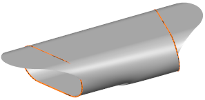
In the following example, for the selected profiles, the Periodic surface option was active:

Back to the Surface type list.
Lofted in two directions
This function creates a surface from a series of "'horizontal" and "vertical" sectional curves. These curves must intersect.
|
Periodic surface |
See Lofted. |
Back to the Surface type list.
Advanced lofted
|
Periodic surface |
See Lofted. |
|
First and second constraint condition: |
|
|
Scale |
The Scale input fields allow you to define the tangent scale factor in order to influence the shape of the created tangent surface(s). |
|
Constraint |
The following options are available:
Clamps are used to create tangency with the selected elements when there are no edges.
|
|
Planar clamp Vector clamp |
Clicking on the  icon switches back into the axis/vector selection mode allowing you to select another direction in the graphic area, using the direction options, if required. Use the icon switches back into the axis/vector selection mode allowing you to select another direction in the graphic area, using the direction options, if required. Use the |
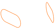
In the following example, a surface is to be created between the two profiles shown in the first image. In the second image, the Planar clamp option was active on both sides along with a positive Scale value. The third image shows the surface created with the Vector clamp option active on the left side and adjustment of the shape using a Scale value:
Back to the Surface type list.
Advanced lofted in two directions
|
First to Fourth constraint condition |
See Tangent patch. |
|
Periodic in U |
Activating this option may allow you to create a periodic surface in U. |
|
Periodic in V |
Activating this option may allow you to create a periodic surface in V. |
Back to the Surface type list.
1 drive multiple shapes
There are no additional options.
Back to the Surface type list.